Network Redundancy for Aerospace and Industrial Operations
How to design network redundancy for mission-critical and industrial sites: diverse paths, redundant switching, fast failover, intact segmentation, and testing.
In a launch support facility, a satellite processing building, or an industrial plant, a network outage can stop operations, leave operators without visibility, or delay a mission. Redundancy addresses that risk when it is designed deliberately: paths that fail independently, failover fast enough for the traffic it carries, and security that holds during the switch. This guide covers how we approach it.
The requirements that actually matter
- What must keep running. Control traffic, safety systems, voice, video, and business applications have different priorities.
- How fast failover must be. Business applications tolerate a few seconds. Some control and protection traffic needs recovery in milliseconds, or no interruption at all.
- When maintenance can happen. If the network can never go down, every component needs a redundant partner that carries the load while it is serviced.
- Security zones. Operational, security, and business networks must stay separated through every failure scenario.
Step 1: Find the single points of failure
Map the network from end devices to the outside world, and ask what happens when each element fails. Common findings:
- A single core switch or firewall
- Uplinks that share one fiber cable, conduit, or cable tray
- One building entrance for all outside circuits
- One internet provider, or two providers whose circuits share a route
- Core services such as DNS, DHCP, authentication, and time servers on a single host
- One power source feeding every network rack
- One person who knows how it all works
Step 2: Build physical path diversity
Redundant equipment connected through the same conduit fails together. Route redundant fiber through separate pathways and building entrances, and favor ring or mesh topologies between buildings over single spans. When buying diverse circuits from carriers, request route documentation and confirm the paths are physically separate, because circuits sold as diverse sometimes share a conduit for part of their route.
Step 3: Make the switching layer redundant
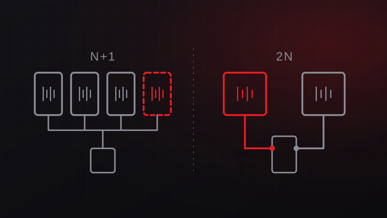
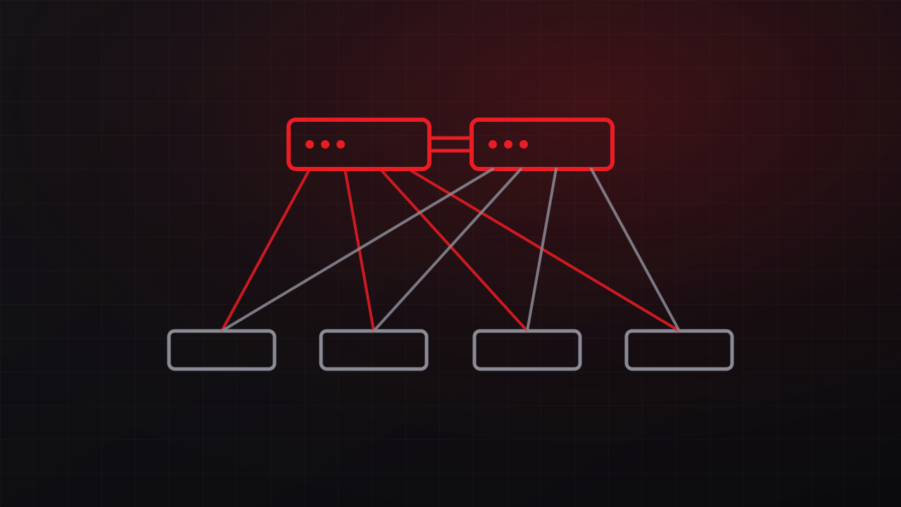
- Redundant core and distribution switches, paired through stacking or multi-chassis link aggregation so either switch can carry the full load.
- Redundant uplinks from each access switch to both core switches, using link aggregation or rapid spanning tree.
- Industrial ring protocols for plant floors and field networks. Protocols such as the Media Redundancy Protocol (MRP, IEC 62439-2) and Device Level Ring (DLR) recover from a break in anywhere from a few milliseconds to a few hundred, depending on the protocol and configuration.
- Zero-recovery-time redundancy for the most demanding traffic. The Parallel Redundancy Protocol (PRP) and High-availability Seamless Redundancy (HSR), both defined in IEC 62439-3, send every frame over two paths so a single failure causes no interruption.
Step 4: Plan redundancy at the edge
- Firewalls in high-availability pairs, with state synchronization so active sessions survive a failover.
- Two WAN or internet paths with different failure modes, such as fiber and fixed wireless, or two carriers on physically separate routes.
- Fast failure detection. Routing protocols paired with Bidirectional Forwarding Detection (BFD) detect a failed path in well under a second, much faster than default routing timers.
Step 5: Power the network like the rest of the critical system
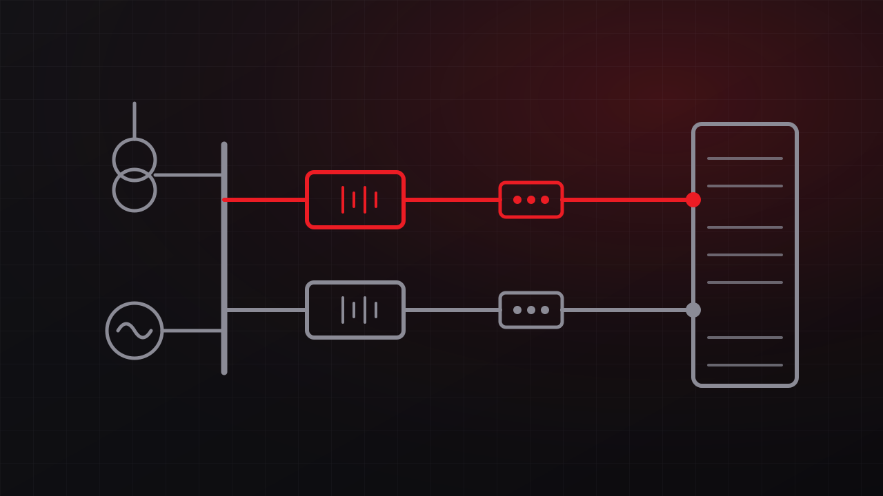
Redundant switches still fail together when they share a power source. Core and distribution switches with dual power supplies should draw from separate circuits, ideally fed by separate UPS systems. Access switches that power phones, cameras, and wireless access points need UPS runtime that matches the facility’s requirements. The principles behind critical power design apply here as well: redundancy is a property of the whole path, from the utility to the switch.
Step 6: Keep segmentation intact during failover
Failover paths are where security quietly erodes. A backup link that bypasses the firewall, a secondary firewall with outdated rules, or a VLAN missing from the redundant path can break isolation between operational and business networks when the primary fails. Mirror security policy on redundant devices, synchronize configurations, and include security checks in failover testing. Our work on a satellite processing facility network separated operational and business systems from the start and was acceptance-tested before handover.
Step 7: Test failover and record the results
Test redundancy before relying on it. During commissioning, disconnect links, power down switches and firewalls, and fail the WAN while measuring how long traffic takes to recover and confirming that monitoring raised the right alarms. Record the results as the baseline. Repeat the tests on a schedule and after significant changes, following a written procedure so the test does not cause the outage it is meant to prevent.
When to bring in help
Designing redundancy for a critical facility means balancing failover speed, security, cost, and maintainability, and the right answer for a control network differs from the right answer for an office LAN. GTech designs and commissions facility networks for aerospace and mission-critical operations and industrial sites, drawing on 30+ combined years supporting operations at Vandenberg Space Force Base. See our networking and telecommunications service, or read how mission-critical facility engineering shapes the rest of our work. Free consultation: 805-979-9897.