Data Center Power Design: A Practical Guide from Utility to Rack
How data center power systems are designed: load planning, N+1 and 2N redundancy, utility service, generators, UPS, rack distribution, studies, and commissioning.
Data center power design determines how much IT load a facility can carry, what happens when a component fails, and whether the system can be maintained while the servers keep running. Most of those decisions are made early, often before the equipment list is final, and they become expensive to change once switchgear and generators are on order.
This guide follows the design in the order an engineer works through it: load, redundancy, utility service, standby generation, UPS systems, distribution to the rack, grounding, studies, monitoring, and commissioning. It applies to purpose-built data centers and colocation fit-outs, and most of it applies at smaller scale to the server rooms and edge sites where many organizations run their critical systems. GTech’s engineering team includes a power engineer who specializes in data center power design, and this is the sequence we use on that work.
Start with the critical load
Every downstream component is sized from the critical load: the power drawn by servers, storage, and network equipment, expressed in kilowatts. An error here carries into every piece of equipment that follows.
A useful load plan answers four questions:
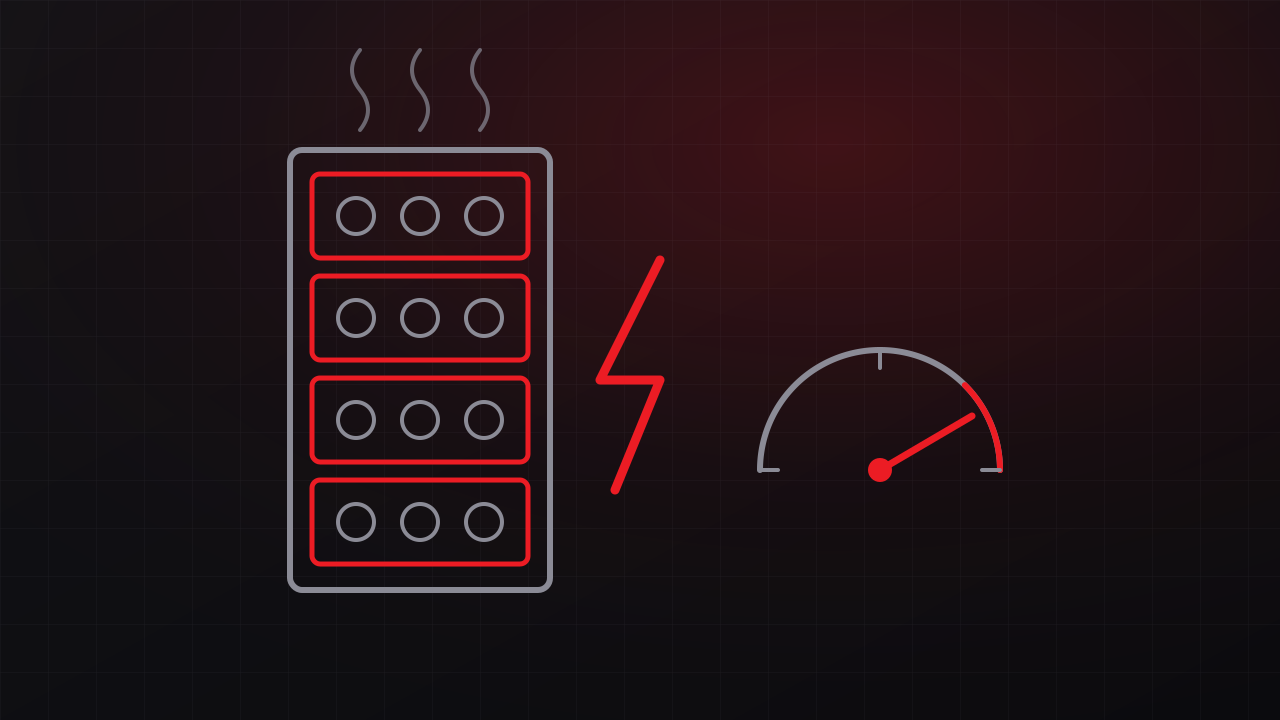
- How many racks, and at what density? Traditional enterprise racks commonly draw a few kilowatts up to the low teens. Racks built around GPU servers draw several times that, and some current liquid-cooled GPU rack systems are specified above 100 kW per rack.
- What is the growth plan? Define the day-one load, the planned phases, and the final build-out. A design sized only for day one runs out of capacity early. A design that installs full build-out capacity on day one ties up capital in equipment that runs lightly loaded for years.
- What else does the facility draw? Cooling, lighting, controls, and electrical losses sit on top of the IT load. The mechanical load depends on the cooling design and the climate, so the electrical and mechanical engineers need to work from the same load plan.
- Which loads need uninterrupted power? IT equipment needs UPS power. Chillers and other large mechanical equipment usually run from generator power and restart after a transfer. High-density rooms heat up quickly while cooling restarts, so fans and pumps often go on UPS power as well, and chiller restart time becomes a design parameter.
Plan from measured data or the manufacturer’s published maximum power. The nameplate rating on a server power supply describes the supply’s capacity and usually overstates what the server draws. Sizing from nameplate ratings produces oversized systems that run inefficiently at low load.
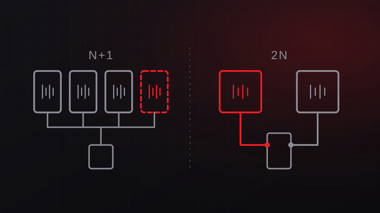
Choose the redundancy level before drawing the one-line
The redundancy level shapes every other decision, so it comes before equipment selection.
| Level | What it means | What it protects against |
|---|---|---|
| N | Exactly enough capacity for the load | Any failure or maintenance event affects the load |
| N+1 | One spare unit beyond what the load needs | Failure or maintenance of any single unit |
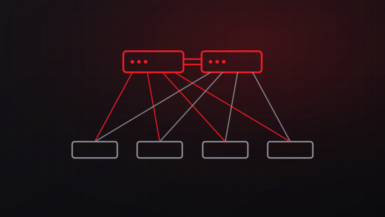
| 2N | Two complete, independent paths, each able to carry the full load | Loss of an entire path |
| 2(N+1) | Two independent paths, each with its own spare unit | Loss of a path plus a unit failure on the other one |
Larger facilities also use distributed redundant designs, in which three or more UPS systems share the reserve capacity. In a common four-system arrangement, each system is loaded to 75 percent or less, so any one can fail and the remaining three absorb its load. Block redundant designs keep a reserve system ready to pick up any failed block through transfer switching. Both approaches deliver much of the protection of 2N with better equipment utilization, in exchange for more complex switching, load management, and operating procedures.
Two points matter most, whatever the label:
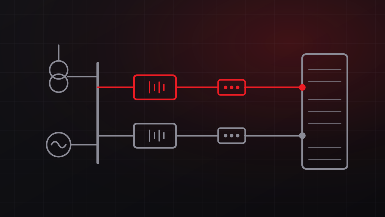
- Redundancy is a property of the whole path. A 2N UPS plant that feeds one shared switchboard still has a single point of failure at that switchboard. Trace every path from the utility to the server power supply, including controls, batteries, breakers, and cable routes.
- The IT equipment has to use it. 2N distribution protects dual-corded equipment with one cord on each side. Single-corded devices need a rack transfer switch, or they go down with their only feed.
Tier ratings describe the same ideas at the facility level. The Uptime Institute’s Tier Standard defines four levels, from basic capacity (Tier I) and redundant components (Tier II) through concurrently maintainable (Tier III) and fault tolerant (Tier IV). ANSI/TIA-942 uses a similar four-level rating. Concurrently maintainable means any component can be taken out of service for planned work without affecting the load. Fault tolerant means the facility also survives any single unplanned failure, which requires the paths to be physically separated so that one event, such as a fire, cannot take out both. Our guide to N+1 and 2N redundancy covers how to choose among these levels.
Confirm utility capacity and schedule early
The utility connection is often the longest lead item on the project. Before design goes far, ask the utility how much capacity is available at the site, what upgrades the project triggers, who pays for them, and how long they will take. On the Central Coast that means PG&E, Southern California Edison, or a municipal utility, depending on the location. Transformer and switchgear lead times have also run long in recent years, so equipment procurement can set the construction schedule.
Design questions at this stage:
- Service voltage. Larger facilities typically take medium-voltage service and step down through owner-owned transformers on site. Smaller facilities and server rooms usually take low-voltage service from a utility transformer.
- Number of feeds. Two utility feeds from separate circuits or substations add resilience where the utility can provide them. Many sites have a single feed, which places more weight on on-site generation.
- Room to grow. Space, conduit, and switchgear sections reserved for future phases cost little during construction compared with retrofitting a live facility.
Size standby generation and transfer equipment
Generators carry the load through outages longer than the UPS batteries can bridge. The Uptime Institute’s Tier Standard treats on-site generation as the data center’s primary power source and the utility as an economic alternative, which affects how generators are rated, fueled, and tested.
- Rating and sizing. Generators carry standby, prime, or continuous ratings, and some manufacturers publish data center ratings for this duty. Size for the full critical and mechanical load plus the step loads the generator sees as equipment restarts after a transfer.
- Redundancy. N+1 generator plants are common. Facilities with the highest availability targets use 2N generation.
- Transfer equipment. Automatic transfer switches suit smaller systems. Larger plants often use paralleling switchgear, which synchronizes multiple generators onto a common bus and adds load in controlled steps.
- Fuel. Store enough fuel for the runtime the business requires, arrange refueling that still works during a regional emergency, and maintain the fuel so it is usable when needed.
- Code separation. Life-safety loads covered by NEC Article 700, such as egress lighting and fire alarm systems, must be kept separate from optional standby loads under Article 702, with their own transfer equipment and wiring. Facilities that a government authority designates as critical operations fall under Article 708.
- Air permits. In California, stationary diesel generators generally require a permit from the local air district, and state rules limit the hours available for maintenance and testing. Build the testing program around those limits.
Design the UPS system
The UPS carries the critical load from the moment utility power fails until generators take over, and it isolates IT equipment from sags, surges, and transients the rest of the time.
- Topology. Double-conversion (online) UPS systems are the standard for data centers because the load runs continuously from the inverter. Many units also offer high-efficiency or eco modes that pass utility power through during normal operation. Those modes save energy and give up some isolation, so choose them deliberately.
- Modular or monolithic. Modular UPS frames let you add power modules as the load grows and build N+1 redundancy inside a single frame. Large facilities often parallel several monolithic units.
- Batteries. Valve-regulated lead-acid (VRLA) batteries remain common. Lithium-ion batteries take less floor space and last longer, and they bring fire code requirements that should be reviewed with the fire authority early in design.
- Runtime. Battery runtime is usually measured in minutes: enough to cover generator start and transfer with margin for a failed first start. Longer runtime adds cost, weight, and space.
- Bypass. Every UPS needs a static bypass for internal faults and a maintenance bypass, preferably an external wraparound, so the UPS can be isolated for service or replacement while the load runs on bypass power.
Size the UPS in kilowatts for the load it will actually carry. UPS efficiency drops at light load, and each side of a 2N system normally runs below half of its rating, so check the manufacturer’s efficiency curve at the loads the system will see in operation.
Plan distribution to the rack
Downstream of the UPS, power flows through switchboards and distribution panels to power distribution units (PDUs) or remote power panels, then to the power strips in each rack. Overhead busway with plug-in tap-off units has become a common alternative to fixed branch circuits because rack power can be added or changed without new conduit.
- Distribution voltage. Many North American data centers distribute 208 V from PDUs with built-in transformers. A 415/240 V distribution system delivers 240 V to IT equipment, can eliminate the transformers inside floor PDUs, and carries more power per circuit, which matters for high-density racks. Most modern server power supplies accept 240 V; confirm it for every device.
- A and B separation. Keep the two feeds to each rack on separate paths from separate sources, label them clearly, and separate them physically where the redundancy level calls for it.
- Loading discipline. Branch circuits serving continuous loads are typically limited to 80 percent of the breaker rating. In a 2N rack, each feed must be able to carry the whole rack if the other fails, so under normal operation each side should run at about 40 percent or less. A rack that drifts above that line works until one feed trips. Then the surviving feed carries the full load, overloads, and trips as well.
- Phase balance. Spread load evenly across the phases of three-phase circuits, and check it with monitoring as equipment changes.
- Single-corded equipment. Plan for it explicitly with rack transfer switches or dedicated circuits so it does not become the weak point in an otherwise redundant rack.
Ground and bond for safety and stability
A data center grounding system clears faults safely, as the NEC requires, and gives electronic equipment a stable reference that limits noise and damage from transients. Plan for:
- A grounding electrode system and bonding design that meets NEC Article 250, including proper grounding at each transformer that creates a separately derived system
- A telecommunications bonding backbone to racks and cable pathways, typically designed to ANSI/TIA-607
- Surge protection at the service entrance and at key distribution points
- Harmonic currents from nonlinear loads, which affect neutral conductor sizing and transformer selection
Run the power system studies
Studies confirm the system is safe to build and operate.
- Short-circuit study. Confirms every breaker, bus, and panel can withstand and interrupt the available fault current.
- Protective device coordination. Sets breakers and relays so a fault trips the nearest device and leaves the rest of the system running. The NEC requires selective coordination for emergency and legally required standby systems, and it is good practice for the critical load.
- Arc flash study. Calculates incident energy at each piece of equipment using IEEE 1584, produces the labels NFPA 70E requires, and informs design choices that reduce the hazard, such as energy-reducing maintenance switching. NFPA 70E calls for the assessment to be updated when the system changes and reviewed at least every five years.
- Load flow and voltage drop. Confirms voltage stays within limits in normal, maintenance, and failure configurations.
Run the studies for every operating mode: utility, generator, UPS bypass, and each maintenance configuration. A generator supplies less fault current than the utility, so protection that coordinates on utility power can behave differently on generator.
Monitor the power path
An electrical power monitoring system (EPMS) watches the power path in real time: utility and generator status, UPS mode and battery health, breaker positions, branch circuit loading, and power quality events. Integrate it with the building management system and, where one exists, the data center infrastructure management (DCIM) platform so operators see alarms in one place and capacity planning uses measured data.
Monitoring also enforces the loading rules above. Branch circuit monitoring that alarms at a set threshold catches an A and B overload before it causes an outage. This is where GTech’s controls and SCADA work overlaps with power design: documented points, tested alarms, and clear operator screens.
Account for efficiency
Power usage effectiveness (PUE) is total facility energy divided by IT energy. The electrical design affects it through transformer losses, UPS efficiency at the actual load, distribution voltage, and how closely installed capacity tracks demand. Right-sized, phased equipment keeps UPS systems and transformers in the efficient part of their load range, which often has the largest effect on electrical losses. In California, Title 24 also sets efficiency requirements for computer rooms, mostly on the cooling side, which changes the mechanical load the electrical system serves.
Commission before the system carries load
Commissioning verifies that the system performs as designed before the critical load depends on it. Data center projects commonly organize commissioning in five levels:
- Factory witness testing of major equipment such as UPS systems, generators, and switchgear
- Delivery and installation inspection against the approved submittals
- Startup and pre-functional checks by manufacturers and contractors
- Functional performance testing of each system individually
- Integrated systems testing (IST), which simulates utility failures with load banks standing in for the IT load and confirms that the UPS, generators, transfer equipment, mechanical systems, and monitoring respond together as designed, including maintenance and failure scenarios
Integrated testing is also the right time to validate the methods of procedure (MOPs) and emergency operating procedures the operations team will use. Outage analyses from the Uptime Institute and others consistently find that procedures and human error play a role in many significant outages, including outages at redundant facilities. The same approach shaped our work on mission-critical aerospace facilities, where systems are commissioned against defined acceptance criteria before they carry the mission.
Apply the same thinking to server rooms and edge sites
Many organizations run critical systems in a server room, a network closet, or an edge enclosure at an industrial site. These rooms carry business-critical load with a fraction of a data center’s protection, and the same design questions apply at smaller scale. Common gaps include:
- A single UPS with no maintenance bypass, so replacing batteries means shutting everything down
- UPS runtime that ends before anyone can respond, with no automated shutdown configured
- Critical equipment sharing a circuit with office loads
- A building generator that serves other loads and misses the server room, or a room with no provision to connect a portable generator
- No monitoring, so the first sign of a failed battery is an outage
Most of these are inexpensive to fix once identified. An assessment of the service, circuits, UPS, loading, and cooling produces a prioritized upgrade list, and it should come before any high-density equipment is added. Our guide to adding GPU servers to an existing server room covers that situation step by step.
Common data center power design mistakes
- Sizing from nameplate ratings and stranding capacity, or sizing from a day-one estimate and running out
- Redundancy that stops at the UPS output, with shared switchboards, controls, or cable routes downstream
- Loading each side of a 2N rack beyond half of its capacity
- Leaving out a maintenance bypass, which turns routine service into a planned outage
- Running studies for the utility configuration only, and skipping generator and bypass operation
- Starting procurement after design is complete, when equipment lead times already control the schedule
- Testing components individually and skipping integrated systems testing
Frequently asked questions
What does data center power design include?
Data center power design covers the complete electrical path that serves IT equipment: utility service, standby generation and transfer equipment, UPS systems, distribution to the rack, grounding and bonding, and monitoring, along with the studies and commissioning that verify the design. The redundancy level ties those systems together.
What is the difference between N+1 and 2N redundancy?
N+1 adds one spare unit beyond what the load needs, so any single unit can fail or be serviced without affecting the load. 2N provides two complete, independent power paths, each able to carry the full load, so an entire path can fail or be shut down for maintenance.
How much UPS runtime does a data center need?
A data center with generators needs enough UPS runtime to carry the load through generator start and transfer, with margin for a failed start attempt, which usually means minutes. A site without generators needs enough runtime for an orderly shutdown, or longer if the business requires it.
Does a small server room need a generator?
A small server room needs a generator when its systems must keep running through outages longer than battery runtime. Many small rooms rely on UPS runtime plus automated shutdown. Where uptime matters through long outages, a generator or a properly designed connection for a portable generator is the practical answer.
How do high-density AI racks change power design?
High-density AI racks raise power per rack by several times, which pushes designs toward higher distribution voltages, busway, larger branch circuits, and liquid cooling, whose pumps and heat rejection equipment add electrical load. They also shorten the time a room can go without cooling, which often moves cooling equipment onto UPS power.
Work with GTech on data center power
GTech’s engineering team includes a power engineer who specializes in data center power design, supported by our electrical, controls, and commissioning practice. We design power systems for data centers, colocation fit-outs, server rooms, and edge sites, and we assess existing facilities that need more capacity or better protection. Our data center power design service covers the full path from utility to rack.
We are based in Santa Maria and support projects across the Central Coast and throughout California. If you are planning a new facility, expanding a server room, or adding high-density racks, contact us or call 805-979-9897 to talk with our engineering team.