N+1 vs. 2N Redundancy: How to Choose for Critical Power
What N, N+1, 2N, and distributed redundancy mean for UPS systems, generators, and distribution, what each one protects against, and how to choose the right level.
Redundancy is the most consequential early decision in critical power design. It sets how many UPS modules, generators, and switchboards you buy, how much floor space the electrical rooms need, and what happens on the day a component fails. The terms get used loosely in proposals, so it helps to pin down what each one means and what it buys.
Start with N
N is the capacity the load needs. If a room’s critical load requires three UPS modules, N is three. A system built to exactly N has no spare: any failure or maintenance activity affects the load.
N can be a reasonable choice for noncritical systems and for sites whose applications fail over to another location. It should be a deliberate choice, made with a clear view of what an outage costs.
N+1: one spare unit
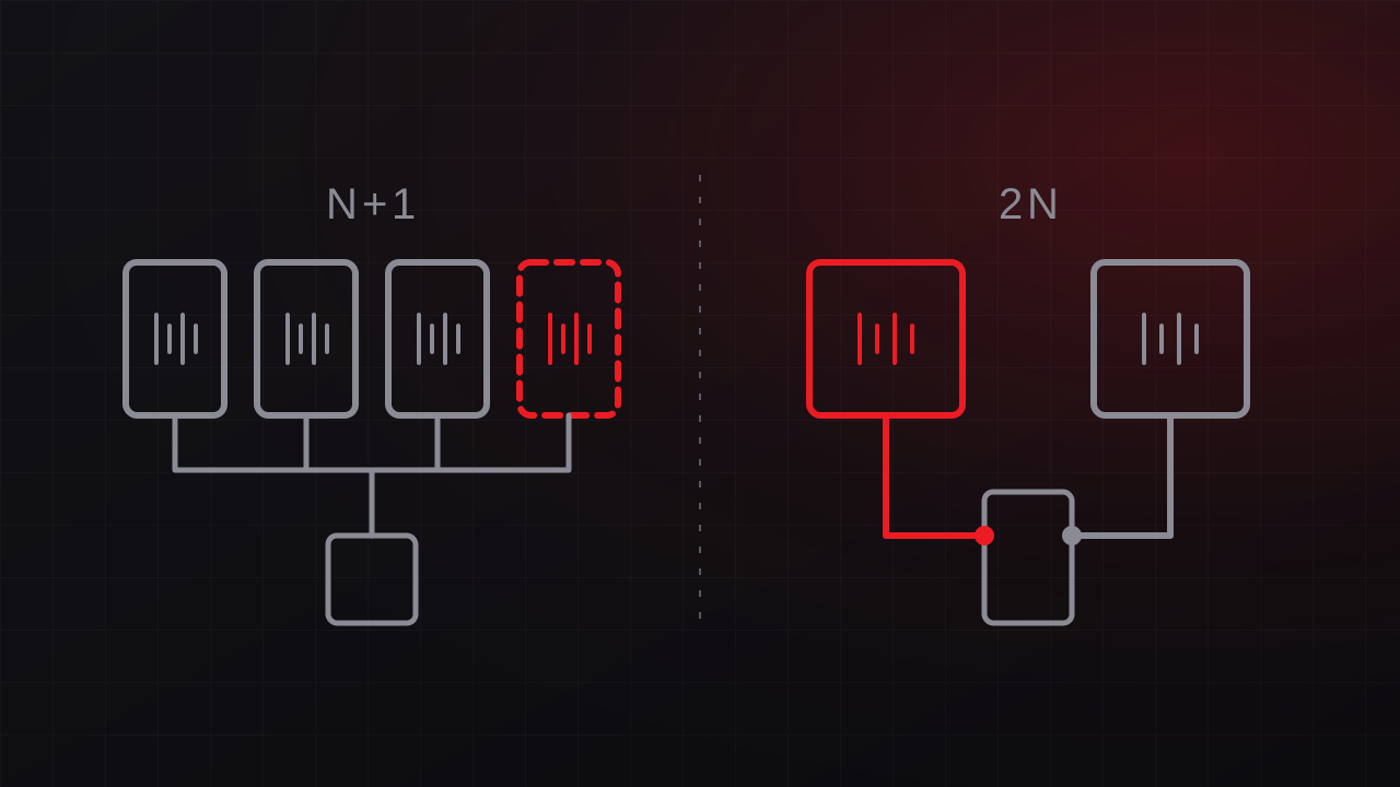
An N+1 system adds one unit beyond what the load requires. With four UPS modules where three can carry the load, any one module can fail or be taken out for service while the other three keep the load running.
N+1 is efficient because you buy one extra unit. Its limitation is scope: the redundancy usually applies to one type of component. The modules may share a single paralleling bus, one output switchboard, one set of controls, and one cable route, and each of those shared elements is a single point of failure. N+1 protects well against the most common failure, a single unit, and less well against a failure in shared infrastructure.
Watch the loading as the facility grows. An N+1 system whose load has grown until it needs all four modules has become an N system. That change happens gradually as equipment is added, so set monitoring alarms on redundancy thresholds to catch it.
2N: two independent systems
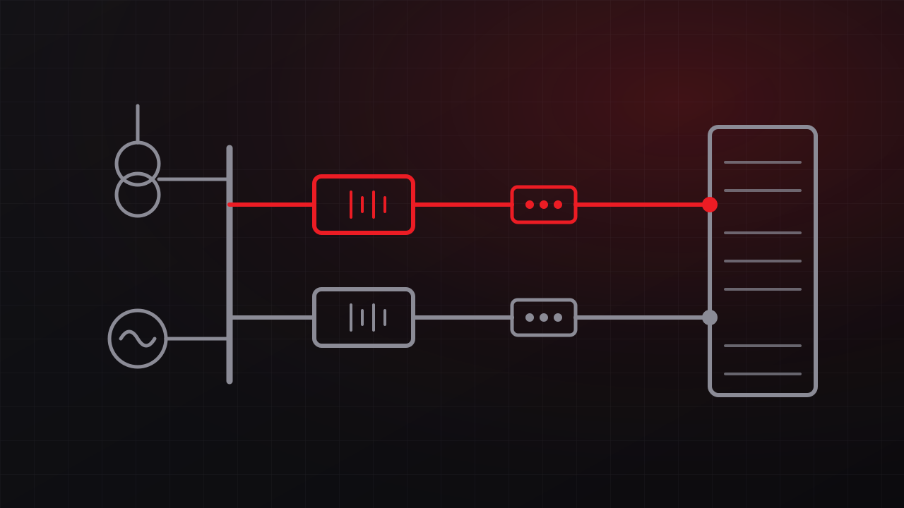
A 2N system provides two complete, independent power paths, commonly called A and B, each able to carry the entire load. Dual-corded IT equipment draws from both. If one path fails or is shut down for maintenance, the other carries everything.
2N costs roughly twice the equipment of an N system, and it demands discipline in operation:
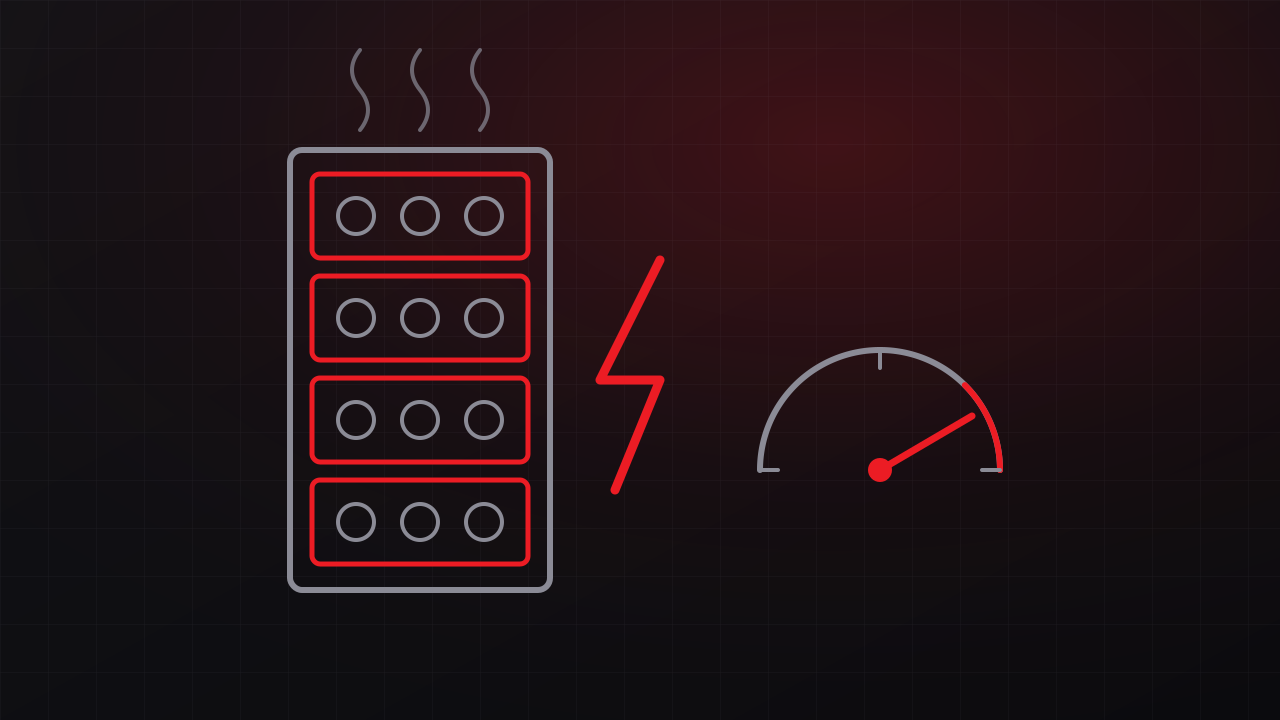
- Each side runs at half load or less. Under normal operation each path carries about half the load and must be able to carry all of it. Branch circuits loaded beyond that line fail in pairs: when one feed trips, the other overloads.
- The independence has to be real. Two UPS systems that share a switchboard, a control network, a battery room, or a cable tray are exposed to a common event.
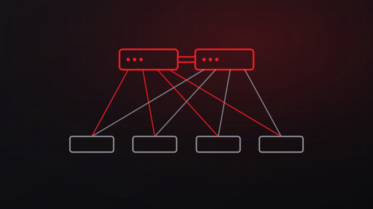
- The IT equipment has to be dual-corded and connected correctly. A server with both cords plugged into the A side receives no protection from the B side. Single-corded devices need a rack transfer switch.
Beyond 2N: 2(N+1), distributed redundant, and block redundant
- 2(N+1) gives each of the two paths its own spare unit, so one path can be down for maintenance while a unit on the other path fails. You will also see the term 2N+1, which adds spare capacity to a 2N system. Ask the designer which arrangement a proposal means.
- Distributed redundant designs use three or more UPS systems and spread each rack’s two cords across different pairs of systems. In a common four-system arrangement, each system is loaded to 75 percent or less, and if one fails, the other three absorb its load. The design delivers much of the protection of 2N with higher equipment utilization, in exchange for more complex load management.
- Block redundant designs, sometimes called catcher designs, dedicate a reserve system that picks up any failed block through transfer switches.
These designs make the most sense at larger scale, where the equipment savings justify the added complexity in design, operation, and procedures.
Concurrent maintainability and fault tolerance
Redundancy counts components. Two related terms describe what the whole system can do:
- Concurrently maintainable means any component, including switchgear and distribution paths, can be shut down for planned work without affecting the load. This corresponds to Tier III in the Uptime Institute’s Tier Standard.
- Fault tolerant means the system also survives any single unplanned failure, with the paths compartmentalized so that one event, such as a fire or a flood, affects only one path. This corresponds to Tier IV.
A facility can have 2N UPS systems and still fall short of both definitions if a shared component or a shared space ties the paths together. That is why a design review traces every path from the utility to the rack and asks what happens when each component is removed.
Redundancy levels at a glance
| Level | Survives | Equipment and complexity |
|---|---|---|
| N | Normal operation only | Least equipment, simple operation |
| N+1 | One unit failure or one unit in maintenance | One extra unit, simple operation |
| Distributed redundant | Loss of any one system | Moderate equipment, complex |
| 2N | Loss of an entire path | Double equipment, moderate |
| 2(N+1) | Loss of a path plus a unit on the other path | Most equipment, moderate |
How to choose
Start with the business questions, then match the architecture:
- What does downtime cost? Include lost revenue, contract penalties, safety consequences, and recovery labor. A system that supports a mission or public safety belongs in a different category from a file server.
- Can the applications fail over? Workloads replicated to another site can tolerate lower power redundancy at each site. Single-site workloads depend entirely on local power.
- Can you schedule maintenance downtime? If the answer is never, the design needs concurrent maintainability.
- Is the IT equipment dual-corded? 2N distribution protects only the equipment that can use both feeds.
- How reliable is the utility at the site? Frequent outages put more weight on generators and their redundancy.
- What do contracts or regulations require? Government and mission customers sometimes specify availability or tier requirements.
- How will the load grow? A modular N+1 design can grow into its capacity. Plan how the redundancy level holds as modules are added.
Redundancy in operation
A redundant design protects the load only if it is operated as designed. Outage analyses from the Uptime Institute and others consistently find that procedures and human error play a role in many significant outages. Written methods of procedure for every switching operation, clearly labeled equipment, monitoring that alarms on loading thresholds, and periodic testing maintain the redundancy the design paid for.
Getting the decision right
Redundancy affects every part of a data center power design, so GTech’s engineering team, including our data center power specialist, works through it early alongside load and growth planning. The same principles apply to the network that runs on that power, covered in our guide to network redundancy for aerospace and industrial operations, and they come from the same discipline behind our mission-critical facility engineering. Free consultation: 805-979-9897.