PLC Retrofit Planning and Commissioning: A Practical Guide
Replacing an aging PLC without disrupting operations takes planning. How to audit the system, choose a migration path, test the logic, and commission the cutover.
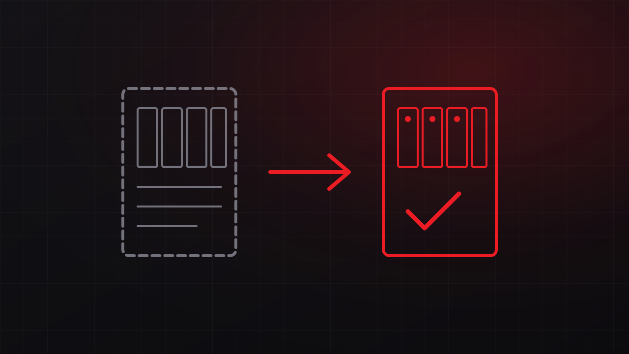
Many water systems, plants, and industrial sites still run on controllers the manufacturer stopped supporting years ago, with spare parts bought from surplus dealers and logic that only a former integrator fully understood. Replacing that controller is often overdue, and it is also one of the riskier projects a facility can take on, because the process has to keep running. This guide covers how to plan and commission a PLC retrofit so the cutover goes smoothly.
The requirements that actually matter
- Downtime tolerance. How long can the process stop, and when? Some systems can stop for a weekend. Others need a cutover measured in hours, with manual operation in between.
- Safety functions. Interlocks, emergency stops, and any safety instrumented functions must be identified and preserved or improved, with the appropriate safety review.
- Connected systems. HMIs, SCADA, historians, remote I/O, drives, and other controllers all depend on the PLC’s addresses and protocols.
- Long-term support. The new platform should match what your staff and support contractors can maintain.
Step 1: Audit what you have
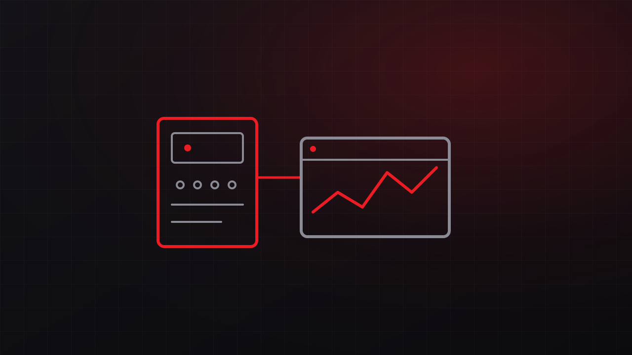
Start by uploading and backing up the existing program, and confirm the backup matches what is running in the controller. Then document:
- The I/O list, with every point’s tag, address, wiring, and field device
- Panel condition: wiring, terminals, power supplies, and space for new hardware
- Networks and protocols, including every device that reads from or writes to the PLC
- HMI screens, alarms, setpoints, and recipes
- Undocumented behavior, gathered by interviewing operators and maintenance staff, who know the sequence that always follows a power blip and the manual workarounds everyone uses
The audit is where most surprises surface, and finding them here costs far less than finding them during the cutover.
Step 2: Choose the migration approach
- Full replacement installs a new controller, new I/O, and often a new panel. It gives the cleanest result and usually requires the longest cutover.
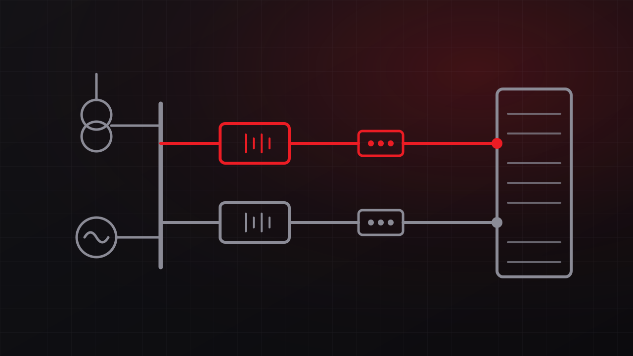
- Phased migration replaces the processor and communications first, keeps the existing I/O temporarily through adapters or remote I/O, and replaces the I/O during later outages. Manufacturers offer migration hardware for several legacy platforms, including wiring conversion systems that let new I/O modules reuse existing field wiring.
- Logic conversion or rewrite. Conversion tools translate an old program into the new platform’s format and provide a useful starting point, and the output still needs line-by-line review. If the old logic is poorly structured, a rewrite from a functional description often produces a system that is easier to support.
The right choice depends on downtime tolerance, panel condition, and budget, and many projects combine approaches.
Step 3: Write the functional description before the code
A functional description states in plain language what the system does: sequences of operation, setpoints, alarms and their responses, interlocks, manual and automatic modes, and the behavior on loss of signal, loss of communications, and power restoration. Operators and engineers review it together. It becomes the test script for commissioning and the reference for everyone who supports the system later.
Step 4: Test before you go to the field
Test the new program against the functional description before it touches the process. Simulation tools and a test panel let you exercise sequences and alarms at a desk. A factory acceptance test (FAT) of the new panel and program, witnessed by the owner, should include abnormal conditions: failed sensors, lost communications, out-of-range values, and power loss followed by restart.
Step 5: Plan the cutover
Write the cutover as a step-by-step method of procedure that lists who does what, in what order, with hold points where the team verifies results before continuing. Include:
- A cutover window chosen for low process demand
- How the process will be operated manually or held in a safe state during the work
- Pre-staged hardware, pre-terminated wiring where possible, and tested backups of everything
- A rollback plan, with the old controller and wiring preserved until the new system is accepted
- Staffing, including operators on site and a clearly designated decision-maker
Step 6: Commission on site
Commissioning proves the installed system works. It usually starts with a point-to-point I/O checkout that confirms every signal from the field device to the HMI screen, continues with functional testing of each sequence against the functional description, and ends with a site acceptance test (SAT) alongside operators. Record results as you go, and close out punch-list items before sign-off. Our water district automation project followed this pattern, with documented logic tested against acceptance criteria before handover.
Step 7: Hand over documentation and training
A retrofit is complete when the owner can support it. Deliver as-built drawings, the commented program, the I/O list, network diagrams, the functional description, and backups stored off site. Train operators on changed screens or behavior, and train maintenance staff on the new hardware. This step keeps the next retrofit from starting with the same unknowns. We covered why documentation matters so much in what PLC and SCADA integration actually involves.
When to bring in help
Small, well-documented systems can sometimes be migrated by in-house staff with manufacturer support. Retrofits that involve public infrastructure, safety functions, multiple sites, or poorly documented legacy logic benefit from an experienced integrator. GTech plans and commissions control system upgrades through our engineering and integration practice for utilities and industrial operations across the Central Coast. Free consultation: 805-979-9897.